This is the second part of a series of blogpost related to the NSX technology, relative to version 4.x
You can find the previous article from this series here:
This is part of a series of blogpost related to NSX:
– Part 1 NSX Layers and Architecture
– Part 3 Logical Switching in NSX (coming soon)
– Part 4 Logical Routing in NSX
– Part 5 Logical Bridging in NSX
– Part 6 Firewall in NSX
– Part 7 Advanced Thread Prevention
– Part 8 Services in NSX
– Part 9 NSX Users and Roles
– Part 10 NSX Federation
Of course before starting deploy the NSX network infrastructure the administrator MUST think about all the components and pre-requisites needed for starting in the right way.
The really first requirement is the installation of the NSX Manager with its requirement like a DNS server with its DNS Records and a usable network, if this is something really new to you, check the official documentation here.
NSX Management Cluster Deploy
The implementation flow regarding the NSX management cluster and relative further step could be summed up in the image below, starting from the OVA (vSphere Only) deployment and then the needed steps from the NSX UI. This is assuming that you have already a working vSphere environment in place of course.

We will see later on this series the steps mentioned above, but for the moment let’s focus on the management cluster so just on the steps from 1 to 4.
Of course for being able to deploy the first NSX manager what is needed it’s a vCenter or a ESXi host that will be used for hosting the manager appliance.
The NSX Manager comes with different form factors, to be decided based on the size of the environment that it will manage:
| Size | CPUs | Memory | Hard Disk Space |
| Small | 4 | 16 | 300 Gb |
| Medium | 6 | 24 | 300 Gb |
| Large | 12 | 48 | 300 Gb |
NSX Manager Ova Deployment
You can find the .ova file for the NSX Manager directly on the VMware Customer Portal
NSX Manager First Login and vCenter Compute Manage registration
NSX Manager deploy node 2 and node 3 from NSX UI plus VIP Configuration.
You can Check the status of the cluster and the relative services via CLI using the following commands from one node:
– get cluster status
– get service
In the video below I’ve also checked the network interface configured on the NSX manager node.
Replace Self-Signed certificates
You can use the NSX-UI to create a new CSR to submit to your Enterprise CA or Internal CA, however there isn’t a procedure through the UI for replacing the certificates, the only way is submitting specific API calls to the NSX Manager as explained here below:
To replace the certificate for a manager node a POST API call must be used:
https://<nsx-mgr>/api/v1/node/service/http?action=apply_certificate&certificate_id=<certificate_id>
To replace the certificate for the VIP, use the following POST API call:
https://<nsx-mgr>/api/v1/node/service/http?action=set_cluster_certificate&certificate_id=<certificate_id>
I’ve written few time ago a blogpost with the procedure for certificate replace using Postman you can check it here.
NSX UI
The User Interface have two main flavors/roles called Policy and Manager.
The Policy mode is the default one that you should use in most of the case:
- it support global manager federation
VMware recommends to use NSX Policy UI as all the new features are implemented only on Policy UI/API.
Be consistent about which mode you use. There are a few reasons to use one mode over the other.
- If you are deploying a new NSX environment, using Policy mode to create and manage your environment is the best choice in most situations.
- Some features are not available in Policy mode. If you need these features, use Manager mode for all configurations.
- If you plan to use NSX Federation, use Policy mode to create all objects. Global Manager supports only Policy mode.
- If you are upgrading from an earlier version of NSX and your configurations were created using the Advanced Networking & Security tab, use Manager mode.
| Policy Mode | Manager Mode |
|---|---|
| Most new deployments should use Policy mode.NSX Federation supports only Policy mode. If you want to use NSX Federation, or might use it in future, use Policy mode. | Deployments which were created using the advanced interface, for example, upgrades from versions before Policy mode was available. |
| NSX Cloud deployments | Deployments which integrate with other plugins. For example, NSX Container Plug-in, Openstack, and other cloud management platforms. |
| Networking features available in Policy mode only:DNS Services and DNS ZonesVPNForwarding policies for NSX Cloud | Forwarding up timer |
| Security features available in Policy mode only:Endpoint ProtectionNetwork Introspection (East-West Service Insertion)Context ProfilesL7 applicationsFQDNNew Distributed Firewall and Gateway Firewall LayoutCategoriesAuto service rulesDrafts | Security features available in Manager mode only:Bridge Firewall |
You can find more about Policy/Manager mode in the official documentation
You can set the user interface preferences in the General Settings tab configuration

Data Plane Preparation
Once the management/control plane is ready and configured properly it’s time to prepare the data plane, understanding the functions of transport zones, transport nodes, N-VDS, VDS, IP Pools, Uplink profiles, transport node preparation and status check.
As written previously the data plane contains different types of transport nodes (ESXi, Bare Metal and NSX Edge) with some functions:
- stateless forwarding, Geneve encapsulation, decapsulation of packets based on the forward tables pushed by the control plane
- scale-out distributed forwarding model to carry the data over the designated source and target transport networks
- logical switching, distributed and central routing, firewall filtering
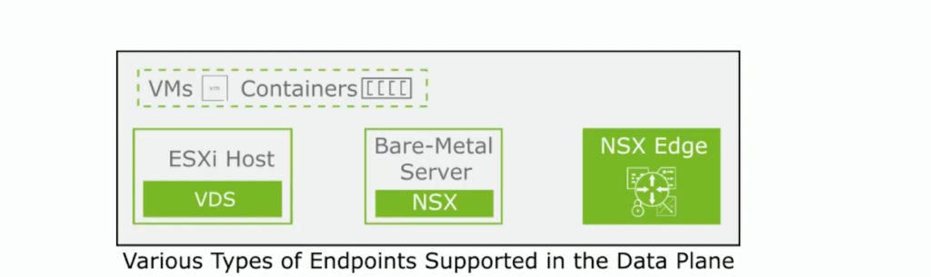
The transport nodes that you can see on the picture above has basically two main components that are defining their architecture inside the NSX SDN solution:
- They have a VDS in the case of ESXI transport nodes where that is the core component for the data plane, and starting from 4.x it’s the only one supported for ESXI.
N-VDS are supported only on NSX Edge nodes and bare-metal transport nodes - The other component is the NSX-Proxy, an agent that is running on all transport nodes and it receives information from the CCP, so basically handles and updates the configuration of the transport nodes.
In terms of connectivity each transport nodes needs connectivity on both Management and Transport network, here based on the requirement / limitation of each environment is possible to use dedicated physical NICs for each traffic or share the traffic on the same physical nic.
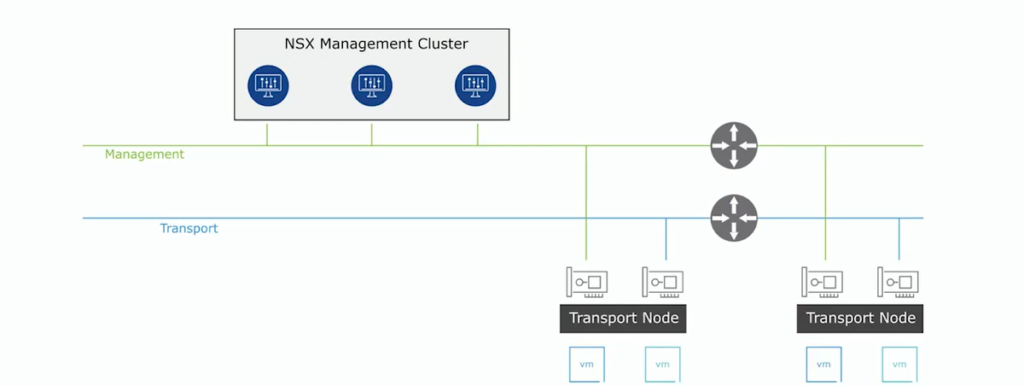
The transport network have its termination on each node on a tunnel endpoint called also TEP.
The TEP basically allow the nodes to join the overlay network and in the end exchange information and traffic between them with the Geneve encapsulation. Of course for joining an ip address is need on this network, so the creation of an IP address pool is helping the administrator the assignment of the ips.
(Each node could have one or more TEP, so in this case calculate in a proper way the network you want to use or the related ip pool)

Transport Zones
Transport Zone is the configuration boundary that define the span of the logical network over the physical infrastructure.
The transport nodes can join two different type of transport zones:
- Overlay: internal tunnel for NSX hosts and Edges that uses Geneve encapsulation for the traffic
- VLAN: used commonly by NSX Edges uplinks to forward north-south connectivity, its use 802.1Q tagged traffic
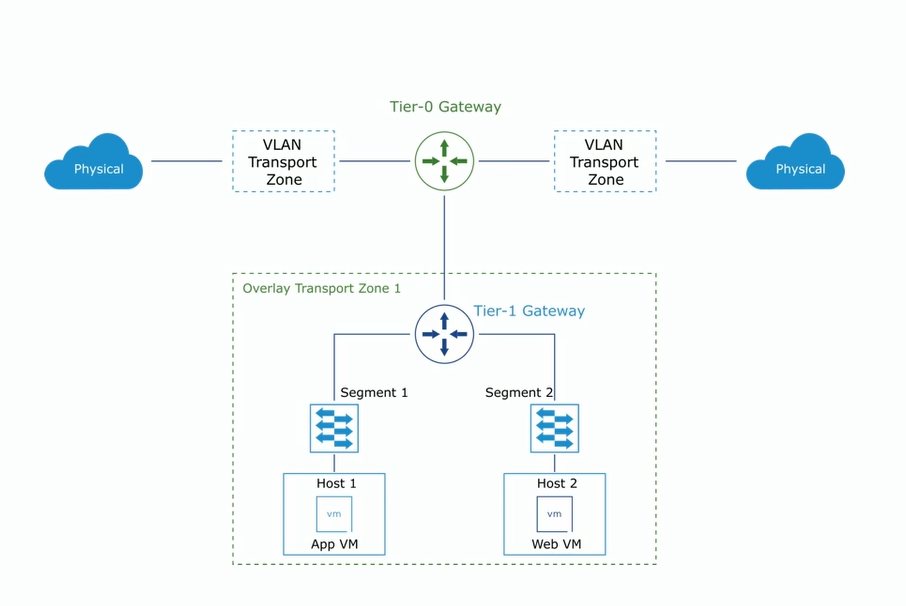
Some rules regarding the transport zones:
- it can have all type of transport nodes inside
- it must not be used as a security boundary
- a transport node can join multiple VLAN transport zone but only one overlay network
- a segment can only be part of one transport zone

Here a simple video that show a quick creation of the two Transport Zones
The VDS can be configured in different modes based on the performance:
- Standard Datapath: default configuration specific for general purposes / normal throughput is expected
- Enhanced Datapath – Performance: based for telecom workloads where high throughput is expected on workloads
- Enhanced Datapath – Standard: interrupt-driven version of Enhanced datapath requires particular type of hardware for being supported
More about the Enhanced Datapath can be found on the official documentation.
Starting from NSX 3.x and vSphere 7.x the VDS become an integrated part of host preparation, definitely facilitate the job of the administrator for preparing the data plane.
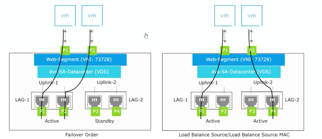
Of Course you can work around the uplink profiles and configure what it seems right for your environment, but this integration is just removing all the previous limitation introduced at beginning with the N-VDS on ESXI host level. Of course completely compatible with multiple NICs and LAGs if needed as showed on the image below.
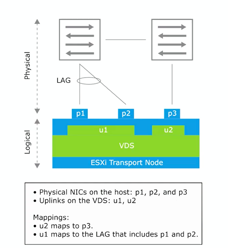
How to configure the association of the uplink on NSX side? Using the Uplink Profiles!
This type of profiles is defining how the VDS connects to the physical network configuring things like:
- transport VLAN used for overlay traffic
- MTU of the uplink (inherited from VDS)
- teaming policy
- create active and stand-by uplinks

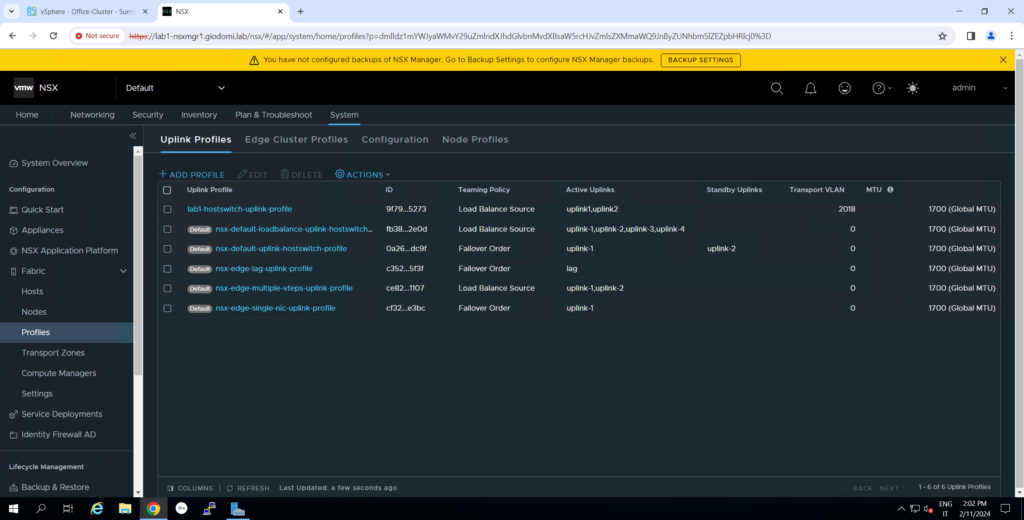
Check default uplink profiles inside NSX and creation of new uplink profile
In my case the TEP traffic should use a specific VLAN 2018
The Uplink Teaming policy configure the redundancy of the uplinks and the failover method, as shown in the video before and also here under.
NSX Uplink profile official documentation
Transport Node Profiles
This profile is the collection of the configuration used for creating and preparing the transport node.
Can be applied to a vSphere cluster to prepare all the nodes present within it with the defined configuration like Transport Zone, VDS Switch configuration, Uplink Profile, Ip assignment and Physical NIC allocation/mapping.
Of course this object allowing the administrator to quick deploy NSX inside the environment from different cluster and can be reused multiple times for avoiding inconsistent configuration issues.

In order to configure transport node profile and work properly remember to check and have:
– NSX to vCenter connection state in Compute Manager
– Transport Zone configured
– ESXi Host to prepared added to vSphere Cluster
– IP address Pool needed for TEP, or DHCP
Creating Transport Node Profile
Attaching TN Profile to vSphere Cluster and Check Status
video attaching transport node profile to vsphere cluster and check the status
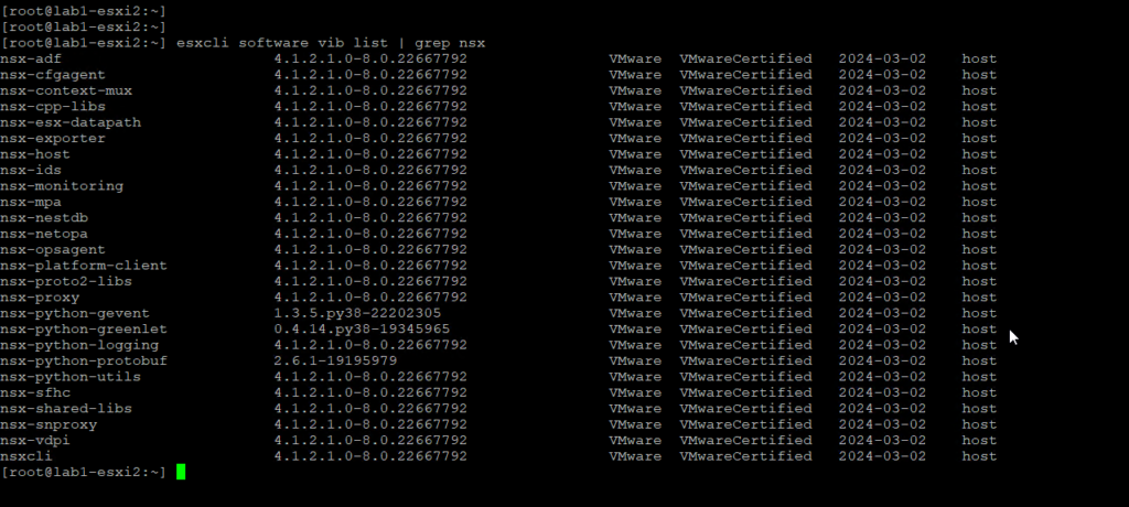
to check if all the needed kernel modules are downloaded and installed on the esxi host you can use this esxcli command -> esxcli software vib list | grep nsx
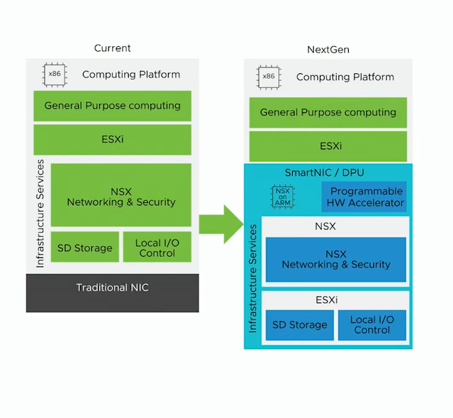
DPU in NSX with vSphere 8
The DPU are the next generation high performant and compute device that will help the virtual workloads and the vSphere/NSX environment achieving full Datapath offloading with higher throughput and low latency.
This new device as you can see on the image below are also allowing to have security services enabled on DPU level, enhance the observability for monitoring, logging, troubleshooting and isolation.
DPU what’s it? Nvidia
Traditional vs DPU Environment
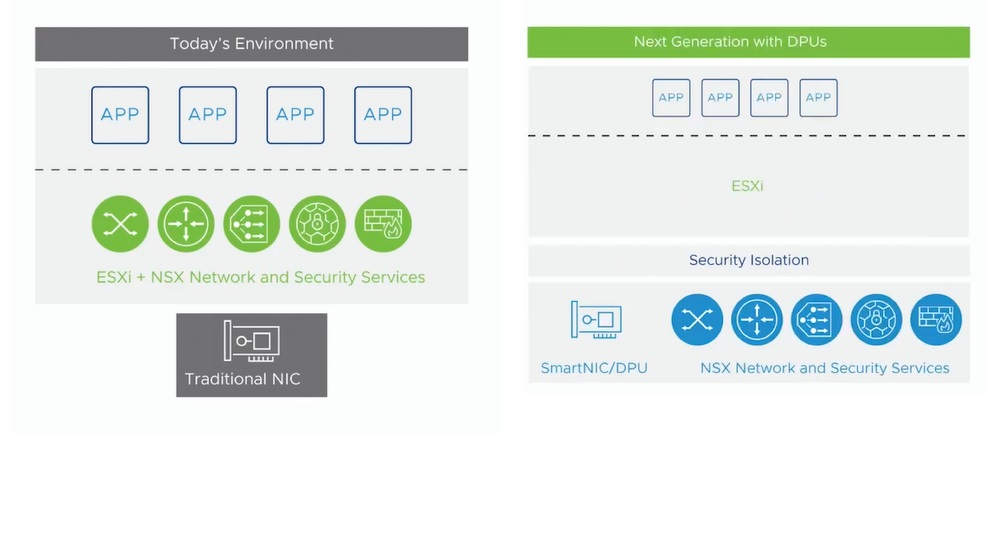
The DPU architecture allow to run inside this new performant device an instance of ESXI with NSX granting the offload of infrastructure services, I/O control and storage.

DPU Resources and White Papers:
– https://lenovopress.lenovo.com/lp1733-secure-and-accelerate-your-infrastructure-nvidia-bluefield-vsphere-vx-series
– https://resources.nvidia.com/en-us-accelerated-networking-resource-library/nvidia-vmware-redis?ncid=partn-vmwa-436301#cid=nbu02_partn-vmwa_en-us
– https://www.vmware.com/content/dam/digitalmarketing/vmware/en/pdf/docs/vmwcb-idc-white-paper-evolving-infrastructure-to-accelerate-and-secure-workloads.pdf
NSX 4.x is supporting these features with DPUs:
- L2 and L3 overlay networking
- L2 VLAN networking
- Packet Capture, IPFIX, Trace Flow and port mirroring
- East-West security with DFW, IDS and IPS
With NSX only one SmartNIC is supported per host, the uplinks of the DPU can be attached to the VDS and if they are two uplinks they can be attached to two different vswitches. You cannot mix uplinks coming from different physical device (SmartNIC and standard NICs) on the same VDS, this is not supported.
This is all for this second blogpost of the NSX 4.x series, if you arrived Thank you for taking the time out to breathe in my words, see you on the next blogpost “NSX 4.x – Part3 NSX Logical Switching”.