This is the third part of a series of blogpost related to the NSX technology, relative version 4.x
You can find other blogpost from this series here:
– Part 1 NSX Layers and Architecture
– Part 2 NSX Infrastructure Preparation
– Part 4 Logical Routing in NSX
– Part 5 Logical Bridging in NSX
– Part 6 Firewall in NSX
– Part 7 Advanced Thread Prevention
– Part 8 Services in NSX
– Part 9 NSX Users and Roles
– Part 10 NSX Federation
Let’s talk about Logical Switching inside NSX, this part will be useful to understand how to deploy, configure and manager layer 2 functionality like segments, segments profiles and of course the Geneve overlay or Generic Network Virtualization Encapsulation.
Logical Switching Architecture
The logical switching of NSX is basically changing the common rules, on top of the existing physical topology its enabling the layer 2 over layer 3 using overlay networks, enhancing the scalability across datacenter and overcome basically the old limit of logical VLAN tagging for example. The span of the NSX network is touching physical hosts and network switches without issues.
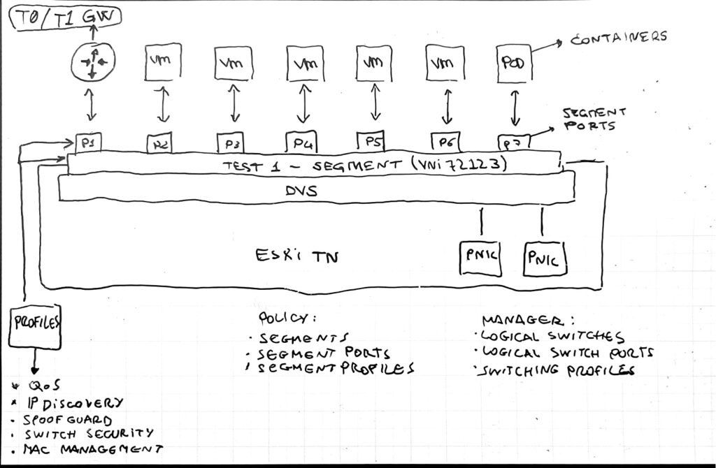
On the image showed above, nsx is creating the segment that is going to be used as L2 domains, showed as port groups in VDS but they are much more than that.
The VM attached to a specific NSX segment are attached with segment port that could be analyzed and controlled via segment profiles for example.
You can see on the below part of the image the differences between policy object and manager object, more or less are basically the same exact thing but configured in different modes. (desired state / imperative with all the details)
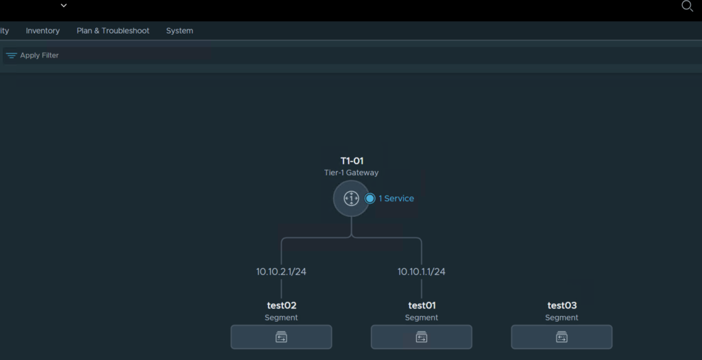
Segments
A segment it’s a L2 broadcast domain that is distributed across the transport nodes, it has a virtual network identified (VNI) that is similar to VLAN ID. The type of segment depends on the parent transport zone, so it could be overlay or VLAN based. The segment created via NSX are showed immediately inside vSphere in a Distributed Port Group flavor, any change must be done from NSX and it’s not doable via vCenter.
How then the traffic is moving inside the NSX infrastructure? It’s done via Tunneling or via TEP interfaces configured in every transport node. This interfaces are used exactly for encapsulating the traffic with Geneve Header and then sent across the TEP then moving inside the physical network.
The Geneve it’s a IETF encapsulation protocol that is doing all the communication work between different transport nodes for example a communication between VMs running on different nodes:
– source TEP encapsulate the frame coming from VM in a Geneve Header
– encapsulated packet is sent via UDP port 6081 to destination TEP
– destination TEP decapsulates the header and deliver the frame to destination VM

An quick example here of Geneve Header format
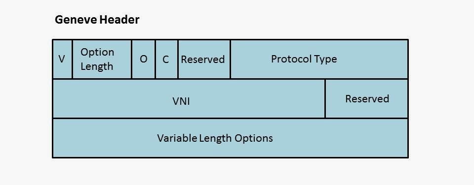
Some quick information about the Geneve header:
– Requires larger MTU (1700)
– UDP
– 8-byte Header
– use port 6081
– 24-bit VNI used for segment identification
– its support TCPDUMP and Wireshark tool
Here under from the communication point of view the flow and the information that are exchanged between the transport nodes when for example a VM wants to communicate with another VM running on different transport node.
1 – Ethernet Frame is sent by VM-1 to Destination Mac Address “DEF”
2 – The frame is encapsulated by TEP on Host 1
3 – The frame is sent with the Geneve Header to the Destination Hypervisor/Host
4 – decapsulation is done in the TEP on the Host 2
5 – The frame is forwarded to destination VM-2

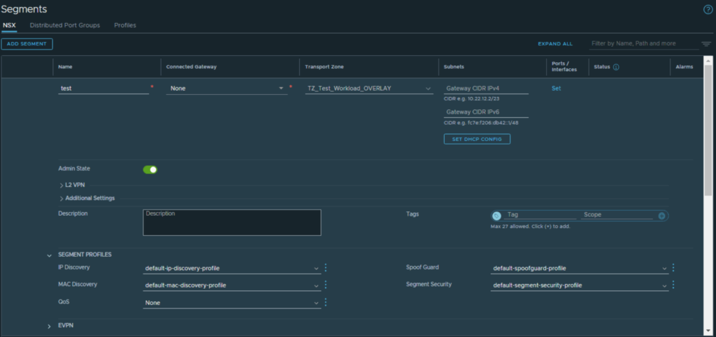
Segment Creation Video
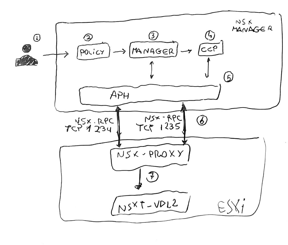
What’s happening behind the scenes when the administrator create a segment could be explained in the following steps here:
1- creation of the segment via NSX UI
2- policy role then pushes the configuration to manager role
3- NSX Manager create the segment information as logical switches (manager object) in the corfu DB
4- Manager role push segment information to CCP
5- CCP send to the APH
6- APH service sends the configuration to the LCP/nsx-proxy via port 1235
7- nsx-proxy agent send the switch configuration to the kernel module nsxt-vdl2 that operate for the creation of the segment on the transport node
If everything is working as it should the segment is showed directly on the vCenter on the VDS chose for the nsx preparation and then it could be used as a “standard” Distributed Port Group.
Once a VM is attached to a NSX Segment, the ESXi host is sending a request to the Management Plane in order to configure the Logical Interface (LIF) on the segment. Then the Manager advertise the CCP that send back the request to the ESXi host where the machine is running and then the VIF is created. (VIF = virtual machine interface).
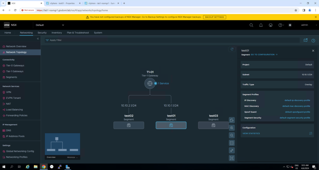
Segments Profiles
This kind of profiles are applicable to the full segment or even the ports with different functions.
There are different types of profile: SpoofGuard, IP Discovery, MAC Discovery, Segment Security and Quality of Service. By default the administrator can found already a good number of default profiles for this type of function.
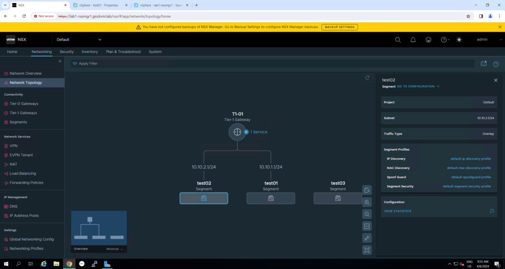
Segment profiles on segment
Segment profiles on segment port
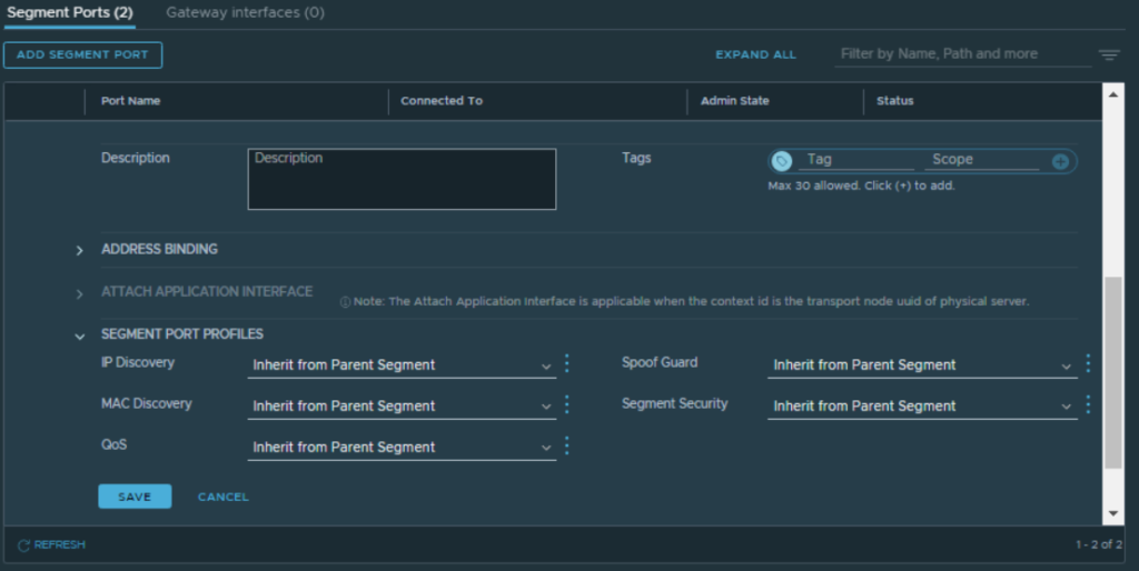
Let’s start go a little bit in details about the profiles mentioned few moments before starting with SpoofGuard.
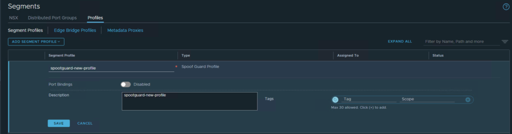
SpoofGuard
It’s used for prevent traffic transmission coming from wrong IP or Mac address for example:
- protect from VM that are trying to have and IP address of another existing running VM
- ensure no alteration of VM ip address
- ensure that DFW rules are not bypassed in any way
The functions used by this profile are the following:
| IP SpoofGuard | Authenticate the Mac and IP address of a packet |
| Mac SpoofGuard | Authenticate the Mac address of a packet |
| Dynamic ARP Inspection | ARP and GARP SpoofGuard and ND SpoofGuard validation are checked against the MAC source, IP source, and IP-MAC source mapping in the ARP, GARP and ND Payload. |
IP Discovery
This function uses the following mechanism to learn MAC and IP addresses from VMs:
– DHCP/DHCPv6 snooping
– ARP Snooping
– VMware Tools
– ND snooping
– Duplicate address detection
All the learned addressed are shared with the CCP to achieve ARP/ND suppression.
Interesting the part regarding the TOEU (trust on every use) and TOFU (trust on first use), by default ARP snooping is in TOFU.

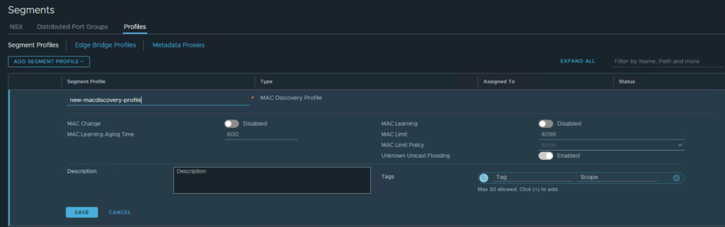
Mac discovery
This one supports MAC learning, eventually MAC address change, unknown unicast flooding, MAC number limits and MAC Policy. Used for allowing for example nested deployments, max number of mac address on particular segment, allowing traffic is MAC change and so on.
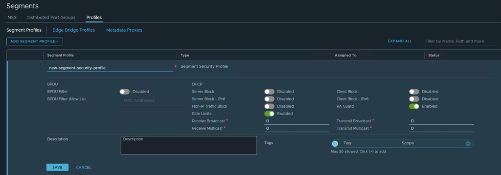
Segment Security
This profiles helps in enforcing stateless L2 and L3 security, protecting segment with filtering attacks blocking for example DHCP Client/Server Requests, broadcast or multicast traffic, MAC filtering and so on.
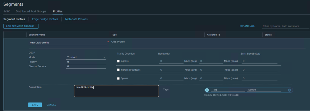
QoS Segment
As standard QoS tagging that’s able to support Class of Service and Differentiated Service Code Point to prioritize certain type of traffic, preventing congestions with traffic shaping and setting also average ingress/egress traffic rate.
Switching Packet Flow
Before going deep on the packet flow we need to know the flow tables involved:
– TEP Table, maintains VNI to TEP binding
– ARP Table, maintains VM MAC to VM IP mapping
– MAC Table maintains VM MAC to TEP IP mapping
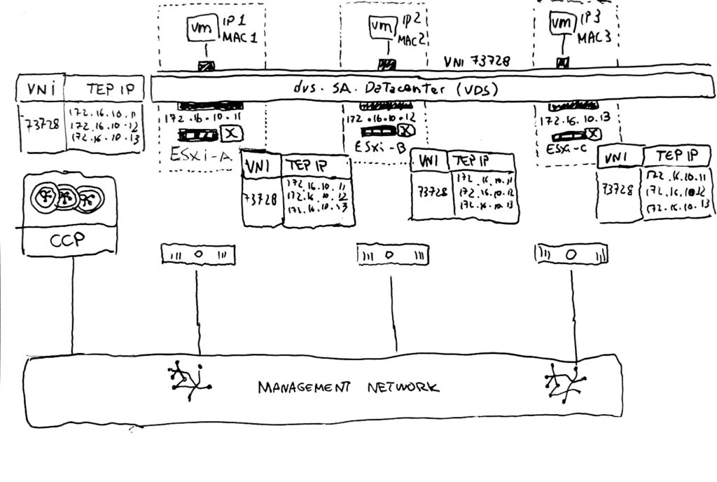
TEP Table
1 – The TAP table is populated with the VNI to TEP mapping when a VM connected to the specific overlay segment is powered-on, at this point the mapping (VNI – TEP IP) is done locally on each Transport Node
2 – Each Transport Node then is pushing the learned VNI to TEP mapping to the CCP
3 – CCP is then saving and maintaining the mappings checking that the TEPs are belonging to different Transport Nodes
4 – CCP send the updated version of the TEP table to all the Transport node where the specific VNI is realized/used (VM powered on)
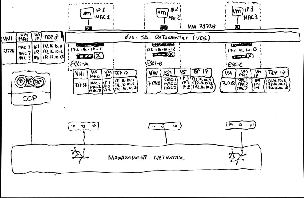
MAC Table
1 – When a Powered-On VM is attached to a segment the VM-MAC to TEP-IP association is saved on the transport node MAC Table (local node)
2 – Each Transport Node pushes to the CCP the learned VM MAC to TEP IP mapping
3 – CCP is then saving and maintaining the mappings checking that the TEPs are belonging to different Transport Nodes
4 – CCP send the updated version of the MAC table to all the Transport node where the specific VNI is realized/used (VM powered on)

ARP Table
NSX it also maintains an ARP table that will be useful for do one simple thing that’s the ARP Suppression.
The Transport Node are learning the IP to MAC mapping using ARP Snooping and DHCP Snooping, this mapping is recorded when a VM start the communication, this information is maintained on CCP and pushed to all Transport Nodes.
1 – Each Transport Node is saving the VM IP to MAC association on the local table
2 – Each Transport Node pushes to the CCP the learned VM IP to MAC mapping
3 – CCP is then saving and maintaining the ARP Table with the information coming from each Transport Node
4 – CCP send the updated version of the ARP table to all the Transport node where the specific VNI is realized/used (VM powered on)
This tables are then used for allowing the perfect communication between machines part of the same segment but running on different host. The communication packet is sent by a VM, encapsulated with the Geneve Header in the Source TEP and forward to the Destination TEP, decapsulated and forwarded to the Destination VM.
One important remark regarding this type of traffic is the BUM (Broadcast, Unknown Unicast, Multicast) that is forwarded to all other VMs that are part of the same segment. This means that a packer must be sent to all the Nodes with VMs connected to the segment. In NSX there are two method of replicating this traffic:
– Hierarchical Two Tier Replication
– Head Replication
The Head Replication is simply creating a lots of copy of the BUM packet and send it directly to all the nodes that are part of the specific VNI / Segment (They have a VM running on the segment where the BUM traffic is needed)
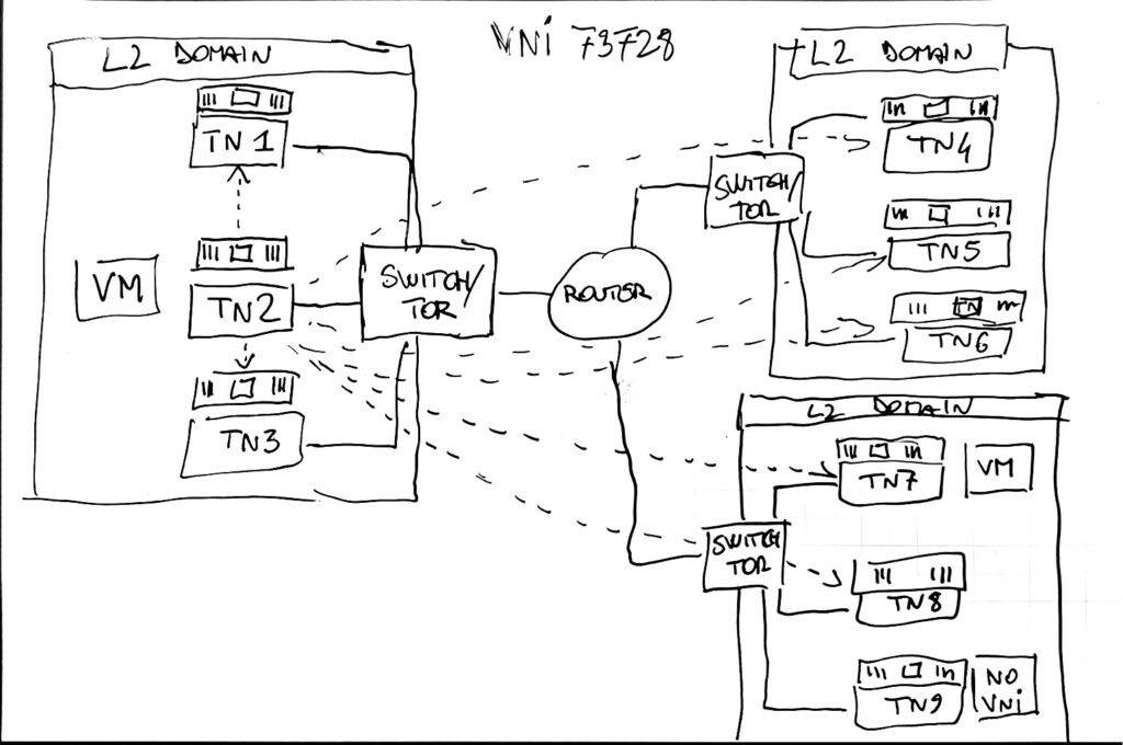
Hierarchical Two-Tier Replication instead the source is sending a copy of the BUM packet to each node inside the same L2 domain. For the Nodes that are not part of the same L2 domain a node is elected as proxy or MTEP. The MTEP Node is then replicating the packet sending to each node part of the same L2 domain.

Understanding BUM Frame Replication on VMware Docs
This is concluding this part related to logical switching, of course if you need more detailed information you can check the official documentation available online.
This next topic will be covered on a separated blogpost: part4 – NSX Logical Routing